Laser Hardening of Gears: Tooth Surface Strengthening with Low Distortion
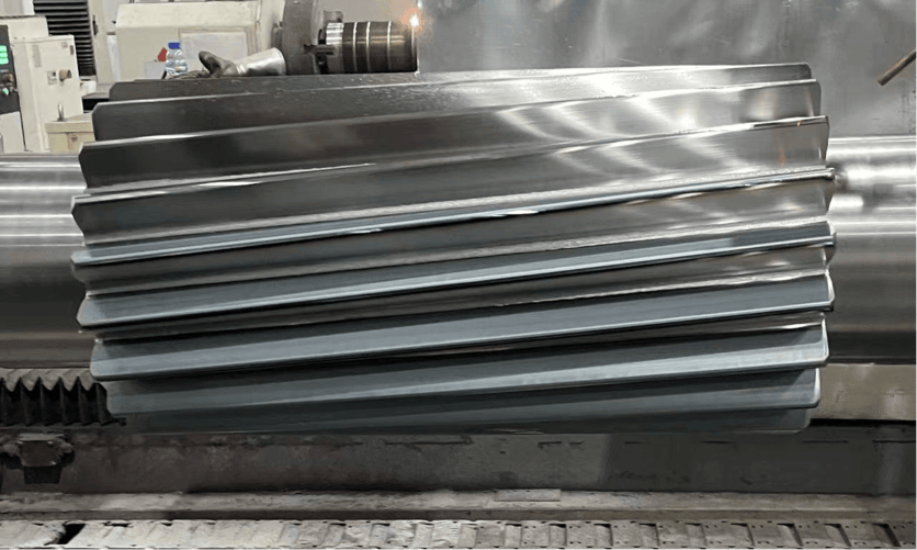
Laser hardening of gears provides localized surface strengthening for tooth flanks exposed to wear and repeated contact loading. By controlling the heat input and scanning path, the process can increase surface hardness while limiting dimensional change and retaining a tough gear core.
This article presents practical processing ranges and application results for gear tooth hardening. The figures describe the applications covered here; they are not guaranteed values for every steel grade, gear geometry or operating condition.
How does laser hardening work on gear teeth?
A laser beam scans the tooth surface and rapidly heats the steel into the austenitizing range without melting it. In the applications described here, the surface heating range is typically 900–1100 °C. Heat then flows into the cooler underlying material, producing rapid self-quenching and a fine martensitic surface layer.
The reported hardened layer depth is 0.3–2.0 mm. This is the depth of the hardened zone, not the total depth affected by heat. The untreated core retains its supporting role, while the surface gains the hardness needed to resist wear. Material suitability and sufficient heat dissipation are essential to the process.
Why use laser surface hardening for gears?
Localized heating supports selective treatment of functional tooth surfaces. In the applications described, gear distortion is within the reported 0.02–0.1 mm range. This can reduce finishing requirements and, where final gear accuracy and surface finish already meet the drawing, may eliminate finish grinding.
Self-quenching avoids the need for quenching oil or a salt bath in the laser hardening step. It also allows treatment to be concentrated on the required areas. Environmental performance should be assessed for the complete production route rather than inferred from the absence of a quench bath.
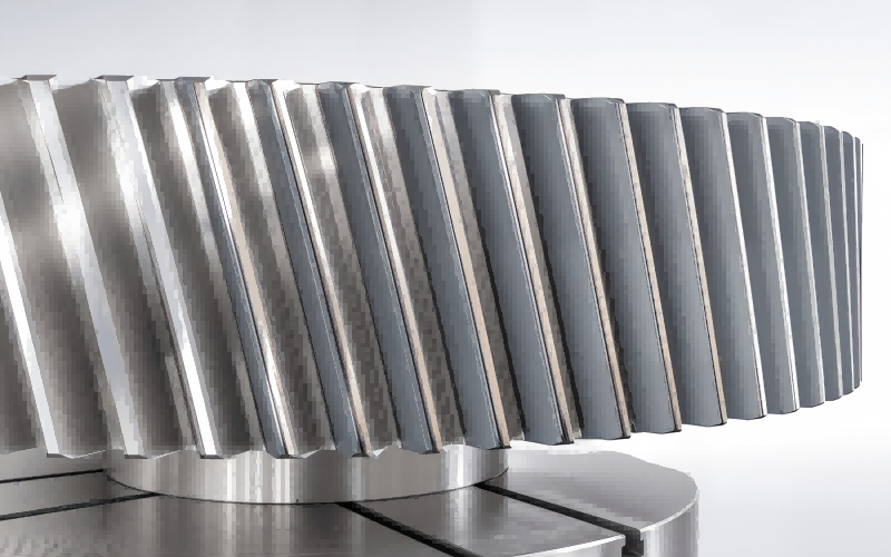
The reported application range covers gear modules of 1–20 mm and includes spur gears, helical gears, spiral bevel gears and internal ring gears. Access to the tooth surface, the optical arrangement and the scanning path determine feasibility for each component.
Applications in heavy-duty and complex gears
Tooth flank hardening for heavily loaded gears
Large gears used in mining machinery, wind power and marine propulsion can operate under demanding contact loads. The applications covered here include contact stresses >1500 MPa. Reported tooth surface hardness increases from HRC 35–40 to HRC 55–62 after laser hardening.
The practical results also report a 2–4-fold improvement in wear life and an increase in the contact fatigue limit. These outcomes depend on the comparison baseline, lubrication, loading and failure criterion. The wear-life result should not be interpreted as the same multiplier for total gearbox life; no numerical increase in contact fatigue limit is specified here.
Uniform hardening of complex tooth profiles
Bevel and spiral bevel gears require careful control of the heating pattern over changing surface geometry. Five-axis coordinated motion and contour-following scanning can maintain the intended beam orientation and working distance while the laser travels along the tooth surface.
In the reported applications, hardened layer thickness variation is <0.1 mm. The treated tooth-tip and root-transition regions are reported to have no soft bands and a smooth hardness gradient. These results depend on the qualified scan strategy and must be checked in the relevant regions rather than assumed from surface appearance.
A rectangular laser spot is matched to the tooth face width. Where the required area can be covered in one track, this reduces the need for adjacent passes and the associated risk of tempering previously hardened material. For multiple-track processing, overlap and the thermal sequence require separate control.
Process parameters and control priorities
The following ranges are retained from the practical application data. They form a process-development window, not a universal recipe: power, speed and spot geometry must be selected together.
Parameter | Reported range / configuration | Control priority |
Laser power | 1000–6000 W | Controls heat input, peak temperature and achievable hardening depth. |
Scanning speed | 5–50 mm/s | Affects heating time and the thermal cycle. |
Laser spot | Rectangular; matched to tooth face width | Reduces adjacent-track reheating where single-track coverage is feasible. |
Overlap ratio | 1%–10% | Applies where adjacent tracks are used; manages overlap coverage and temper-softened zones. |
Managing heat input and overlap
Insufficient heating can leave the required zone incompletely hardened, while excessive heating can cause surface melting or unwanted thermal effects. Temperature monitoring, scan speed and beam positioning should therefore be considered together. The 1%–10% overlap range applies to multi-track treatment; it is not a mandatory overlap for a tooth flank covered by a single width-matched track.
Laser hardening vs. induction hardening and carburizing
The numerical comparison below preserves the original application ranges. These are reference values for the cases summarized, not universal process limits or a controlled comparison under identical conditions.
Metric | Laser hardening | Induction hardening | Carburizing and quenching |
Hardened layer depth (mm) | 0.3–2.0 | 1.0–5.0 | 0.5–2.0 |
Distortion (mm) | 0.02–0.1 | 0.05–0.3 | 0.1–0.4 |
Gear module (mm) | 1–20 | >5 in the source comparison | No module limit specified in the source |
Hardening depth definitions and distortion measurements must be aligned before using these figures to select a process. The induction module entry describes the source comparison, not a physical lower limit of induction hardening. Carburizing feasibility also depends on material, geometry and equipment capacity.
The source applications describe little or no subsequent machining after laser hardening, finish grinding after induction hardening, and gear grinding plus shot peening after carburizing. These are application-specific production routes. Grinding depends on final accuracy and surface requirements; shot peening is a separate design or fatigue-performance requirement, not an obligatory step after every carburizing treatment.
Questions to ask before specifying gear laser hardening
What hardness and hardened depth can be achieved?
The reported surface hardness after treatment is HRC 55–62, with a hardened layer depth of 0.3–2.0 mm. Achievable values depend on the steel grade, initial heat treatment, tooth geometry and thermal cycle. Agree on the hardness test locations and the criterion used to define hardened depth before qualification.
Can laser hardening eliminate gear grinding?
It can in applications where the measured post-treatment geometry and finish meet the drawing. The reported distortion range of 0.02–0.1 mm is a useful reference, but it does not by itself prove that a particular gear meets its accuracy class.
How can soft bands between hardened tracks be reduced?
Match the rectangular spot width to the required tooth surface coverage where possible. If adjacent tracks are necessary, qualify the overlap ratio and sequence, and check hardness across the overlap as well as at tooth tips and root transitions.
Can internal ring gears and bevel gears be treated?
They are included in the reported application scope. Feasibility depends on optical access, working distance, beam orientation and coordinated motion. A review of the actual gear drawing is necessary before selecting the treatment strategy.