Why Choose Powder-Fed Laser Cladding for Large Industrial Components?
Replacing a large shaft, roll, cylinder or valve component can involve substantial material cost, long procurement lead times and difficult transportation. Yet the damage may occupy only a bearing seat, sealing surface or other limited working zone. Powder-fed laser cladding can be a sound engineering choice when the underlying component remains serviceable and the required alloy can be deposited, inspected and finish-machined without unacceptable distortion or cracking.
Size alone does not make a component suitable. Large parts change the economics of replacement and impose distinct demands on deposition rate, heat management, motion, powder delivery and final tolerances. The decision is therefore not simply whether laser cladding works, but whether a qualified powder-fed process offers a better total repair route than wire-fed deposition, conventional weld overlay, a simpler surface treatment or replacement.
When Does Powder-Fed Laser Cladding Make Sense?
The strongest case is a high-value component with localized wear, corrosion or modest dimensional loss, an intact load-bearing core, and a surface requirement that differs from the substrate. The method can rebuild a defined zone or apply a corrosion- or wear-resistant alloy without manufacturing an entire replacement. Avoiding a long replacement lead time may be as important as the deposition cost itself.
A repair still needs enough access for the cladding head and shielding, a compatible substrate and filler alloy, a realistic machining allowance and an inspection route. If a long, wide surface needs thick build-up, productivity may become the controlling factor; if a narrow bearing seat needs precise placement, deposition control may matter more than maximum kilograms per hour.
Why Large Components Change the Process Design
The scale and shape of the workpiece influence almost every process choice. An engineering plan should translate the component geometry into the following decisions:
Large-component factor | Engineering consequence |
Surface area → deposition productivity | A broad roll or cylinder needs a feasible coverage rate and track-overlap strategy. Calculate total deposit volume, effective deposition rate, expected powder utilization and downtime; a small repair patch and a full-length overlay are very different jobs. |
Mass → thermal behavior | High mass may act as a heat sink early in a pass, but repeated tracks and long processing times can still create local heat accumulation and changing interpass temperatures. Monitor temperature, distortion and cracking risk rather than assuming a heavy part cannot overheat. |
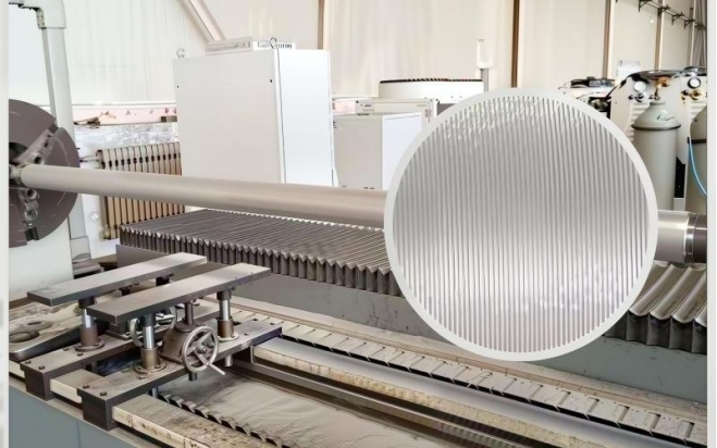
Length/diameter → motion architecture | Long shafts and large-diameter rolls may require a turning fixture, synchronised rotation and axial travel, or a gantry/robot with adequate reach. Verify payload, runout, straightness, working distance and collision clearance. |
Repair zone → beam size | A narrow journal, groove or seal land favors controlled bead width and access. A broad area may benefit from a larger spot or higher-throughput strategy, subject to fusion, dilution and bead-quality qualification. |
Processing time → powder/feed stability | Long toolpaths amplify small changes in feed rate, carrier gas, powder flow, nozzle condition and standoff. Calibrate feeding, maintain shielding and plan monitoring and interruption/restart procedures. |
Final tolerance → machining allowance | The as-deposited bead is not a finished bearing or sealing surface. Set sufficient stock for turning/grinding while limiting excess build-up; include inspection and machining time in the repair economics. |
How the Powder-Fed Process Addresses the Repair
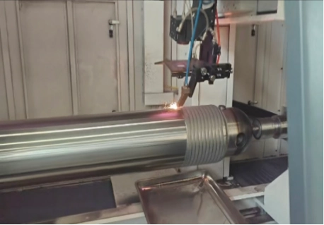
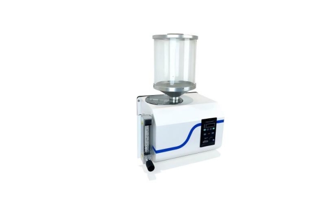
In powder-fed laser cladding, a feeder delivers metallic powder through a nozzle into a laser-generated melt pool. As the tool and workpiece move relative to each other, successive tracks solidify and overlap to rebuild the specified region. The deposited layer forms a metallurgical bond with the substrate when material compatibility and process parameters are properly controlled.
Compared with many conventional weld-overlay processes, laser cladding can provide more localized heat input and a narrower heat-affected region when the process window is properly controlled. This can be valuable near precision journals or sealing lands, but it does not eliminate residual stress, substrate dilution, distortion or cracking. Heat input must be evaluated over the entire long-path repair, not just an individual bead.
Powder-Fed vs Wire-Fed vs Conventional Weld Overlay
No deposition method is universally best for large parts. Selection depends on the repair geometry, alloy availability, productivity target and acceptable rework.
Option | Where it can fit | Trade-off to verify |
Powder-fed laser cladding | Controlled placement on irregular or limited repair zones; access to a broad range of powder alloys; useful when bead geometry and surface functionality matter. | Powder overspray and capture losses; feed consistency and shielding demands; substantial equipment and safety requirements. |
Wire-fed laser deposition | Often attractive for long, accessible paths or higher-volume build-up; high feedstock utilization with less loose powder handling. | Wire approach angle, stable melting and access can constrain complex geometries; alloy choices depend on available wire; finishing remains necessary. |
Conventional weld overlay | Mature, widely available approach for robust or extensive build-up; may offer strong economics for large volumes. | Often higher overall heat input and greater distortion/HAZ management demands, depending on process and parameters; may require more machining. |
Simple repair or replacement | Grinding, polishing, local machining or sleeve replacement may be cheaper when damage is shallow; full replacement addresses extensive structural failure. | Surface-only measures cannot restore substantial missing stock or deliver an engineered alloy layer; replacement can have long lead times and high handling cost. |
For example, a narrow worn journal on an otherwise sound heavy shaft may favor powder-fed cladding because deposition can be confined to the worn seat and followed by grinding. A full-length, thick build-up on a readily accessible roll could favor wire-fed laser deposition or a conventional overlay if throughput and total cost outweigh the benefit of narrower tracks. These are screening examples, not substitutes for trials.
Thermal Accumulation and Long-Path Consistency
The large mass of a component does not guarantee dimensional stability. A long sequence of overlapping passes changes local temperature, melt-pool response and residual-stress distribution. Process planning should specify travel path, track overlap, interpass temperature, preheat where appropriate, cooling pauses and any required post-process treatment. Heat-sensitive or crack-prone substrate/alloy combinations may be unsuitable without a proven procedure.
For large areas, the effective rate is more useful than a headline deposition rate. Include non-depositing travel, repositioning, powder changes, inspection, interruptions and machining. The feeder and nozzle must maintain stable flow during extended operation; drift can produce inconsistent bead height and thickness that later increase grinding time or cause insufficient material at the final dimension.
Workpiece Handling, Access and Post-Machining
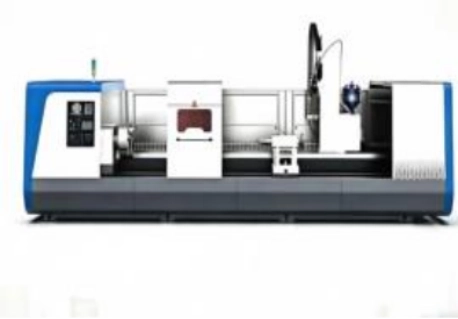
A large part may be constrained more by the machine envelope and fixture than by laser power. Before committing, confirm maximum workpiece mass, turning diameter, length between supports, centreline height, head reach, internal access, and safe extraction of dust and fumes. For cylindrical components, coordinated rotary and linear axes can keep the bead location consistent along the length. Inner bores may demand specialised optics and a minimum clearance.
Final dimensional requirements should be set before deposition. Bearing seats, seals and mating diameters typically need machining or grinding after cladding; the plan should include deposit thickness above the finished size, allowances for runout and distortion, an achievable finishing process, and nondestructive inspection where the duty is critical. A repair that cannot be finished or verified economically is not a successful repair.
Alloy and Equipment Selection for a Large-Part Job
Filler choice follows the service failure mode, not simply the highest hardness. Iron-based powders may suit particular wear repairs; nickel-based options may suit selected corrosion-and-wear exposures; cobalt-based alloys may be considered for demanding hot-wear duties; and copper-based alloys serve specialised applications. Actual suitability depends on substrate metallurgy, service temperature, contact loading, dilution, crack sensitivity and applicable specifications.
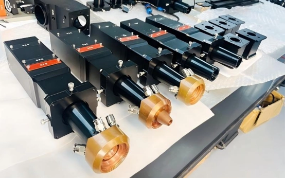
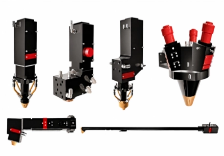
LZ Optical lists laser cladding equipment, outer-surface coaxial powder-feed heads, annular-beam head configurations, gravity/continuous/air-driven powder feeders and iron-, nickel- and copper-based cladding powders. For a large component, evaluate these as one integrated system: laser output, spot size, access, powder delivery, shielding, cooling, motion control and post-machining capability must work together.
When Is Laser Cladding the Wrong Repair?
· The component has through-cracks, extensive fatigue damage, unacceptable distortion or insufficient remaining wall thickness; an added surface layer does not restore a structurally failed core.
· The damaged region cannot be reached with the required nozzle angle, standoff, shielding, scanning path or machining tools.
· The substrate and coating combination has an unacceptable crack, dilution or service-performance risk, and no qualified procedure is available.
· The coverage area or build-up volume makes powder usage, cycle time, fixturing and finishing less economical than a faster overlay, sleeve, machining-only repair or replacement.
· Inspection, documented quality requirements or tight final tolerances cannot be achieved within the available equipment and budget.
Practical Specification Checklist
Send the supplier a component drawing and, where possible, measured damage map. State substrate grade, existing surface condition, required service properties, total length and diameter, component mass, accessible repair zone, targeted build-up thickness, final tolerance, planned finishing route and acceptance tests. Ask for a representative trial, including cross-section or bond assessment where relevant, before authorising the full-length production path.
For cost comparison, request a complete route estimate: preparation, transport and handling, fixtures, cladding time, consumables, powder utilization, machining, inspection, and downtime. The economical choice may differ substantially between a localized recovery and a near-total surface rebuild.
Conclusion
Powder-fed laser cladding is particularly compelling for large industrial components when replacement is expensive, the load-bearing core remains sound and only selected surfaces need rebuilding or upgrading. Its value lies in precise alloy placement and a potentially more localized thermal process—not an automatic advantage for every large surface. Deposition productivity, long-path feed stability, fixture capacity, thermal history, machining allowance and repair qualification determine whether it is the right engineering and commercial decision. LZ Optical can use the component drawing and repair requirements to help identify appropriate powder-feed heads, feeders and motion equipment, while also comparing wire-based alternatives where higher-volume deposition may be more practical.
FAQs
Q: When is powder-fed laser cladding preferable to wire-fed deposition for a large component?
A: It can be preferable when the repair is relatively localized or geometrically complex, requires controlled bead placement or calls for an alloy more readily available in powder form. Wire-fed deposition may be more attractive for long, accessible build-up paths with high material-utilization and throughput priorities. Trials should compare the complete finished-part cost.
Q: What limits the size of a component that can be laser clad?
A: The practical limits are the machine/robot travel and reach, workpiece weight and positioning capacity, available rotary support, safe laser and powder containment, nozzle access, thermal management, and the ability to machine and inspect the finished region. There is no universal maximum size independent of the equipment and geometry.
Q: When is a large component not suitable for laser cladding repair?
A: It is a poor candidate when the parent metal has serious structural cracking or inadequate remaining section, the repair zone cannot be accessed, alloy compatibility cannot be qualified, or thermal distortion and finishing tolerances cannot be controlled. It may also be uneconomic when extensive deposition and machining cost more than overlay alternatives or replacement.