What Controls Improve Powder Feed Consistency in Laser Cladding?
Laser cladding may appear stable at the start of a shift, yet track quality can vary after several hours of operation. Small changes in powder flow rate can affect bead width, layer height, dilution, and material consumption. Selecting a feeder with suitable capacity is only one part of process planning. Powder delivery to the melt pool depends on powder properties, feeder design, delivery-line layout, cladding-head design, and process control.
In directed energy deposition, in-process monitoring and adaptive control help identify deviations during production. Detecting changes during deposition allows teams to respond before end-of-process inspection. Control begins with the powder and extends across the feeder, delivery line, cladding head, motion system, and process parameters.
Why Powder Feed Consistency Matters
The powder feed rate must be matched to laser power and travel speed. If the powder stream increases or drops suddenly, the melt pool may receive too much or too little material. This can affect coating height, surface quality, and bonding.
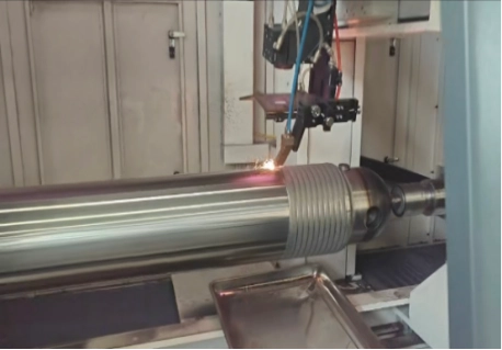
These issues are more likely to appear during long production runs and on parts with irregular contours. A setting that works on a short test piece may not remain stable on a production component such as a shaft or roller. Feeding conditions can also differ between an internal bore and an external surface.
Signs of an Unsteady Powder Stream
Operators can often identify insufficient or unstable powder delivery by observing the deposited track. Visible coating defects may also indicate feed-related problems. Common signs include:
l Bead width or height shifting during a single pass
l Patchy material deposition with rough areas and scattered powder near the printing track.
l Inconsistent results on seemingly identical parts, using identical machine settings.
l Higher powder usage than estimated in the original process plan.
l Powder bridging, sudden surging, or complete blockages at the feeder outlet.
These symptoms do not always indicate a faulty feeder. Powder condition, gas supply, nozzle wear, and programmed motion can produce similar defects. Inspect the full delivery path before attempting to correct the issue by changing laser power.
Start With the Powder
Even powders sold under the same alloy designation can differ in ways that affect flow through the feeder and nozzle. Relevant properties include particle-size distribution, particle morphology, sphericity, satellites, surface condition, and moisture content. Moisture pickup can significantly reduce powder flowability and increase the risk of agglomeration or unstable feeding. A broad particle-size distribution may also promote separation during handling.
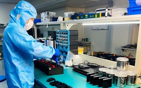
Material selection depends on the base substrate and the component’s service environment. Iron-based powders are used for many wear-repair applications, while nickel-based alloys may suit parts exposed to corrosive conditions. LZ Optical provides several cladding alloy powders, including nickel-based alloy powder. The selected grade should be compatible with the base metal, coating requirements, and feeding method.
Handling and Batch Checks
Verify powder quality before each production run. Keep the material clean and dry, and follow the supplier’s storage instructions. Confirm that the production batch matches the qualified batch. If flow changes unexpectedly, record the powder lot number and inspect the material before assuming that machine settings are responsible.
Ask the supplier for the particle-size range of the wear-resistant alloy powder and the recommended feeding conditions. These details establish a baseline and help teams investigate differences between batches.
Match the Feeder and Delivery Path to the Job
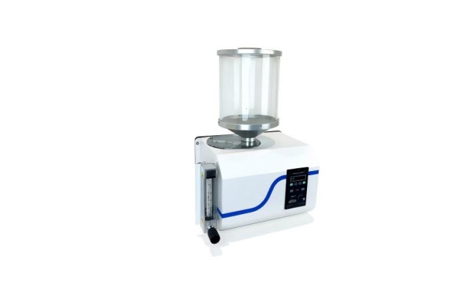
A powder feeder should deliver material consistently across the planned operating range. Performance depends on feeder type, hopper behavior, gas settings, and the distance between the feeder and cladding head. A stable reading on the feeder display does not by itself confirm that the same mass flow reaches the workpiece.
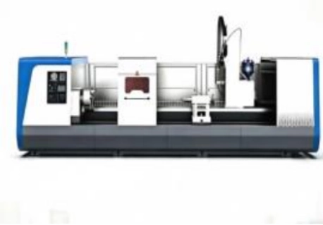
Powder feeders can use different metering mechanisms and carrier-gas configurations depending on powder properties, target mass-flow rate, number of channels, and required operating time. Selection should also account for delivery-line layout, process requirements, and integration with the cladding system. The laser cladding equipment range covers equipment categories for a range of industrial applications.
Check the Full Route From Hopper to Nozzle
Powder can accumulate or settle in hoses and change speed as it passes through fittings. Long delivery lines, tight bends, machine vibration, and feeder placement can affect flow stability. Review the following areas:
l Hopper physical condition and the actual powder level during operation
l Total hose length, sharp bends, loose connections, and visible wear
l Carrier-gas supply pressure and overall flow stability
l Accurate feeder calibration across the planned operating limits
l Routine cleaning and strict inspection schedules for both the delivery line and nozzle
Increasing gas flow is not a universal solution. Excess gas can disrupt powder transport and change how the powder stream interacts with the cladding zone. Tune feeder and gas settings together, then verify system performance with a controlled test.
Choose a Cladding Head That Supports Stable Delivery
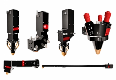
The processing head defines the beam and powder geometry and the nominal working-distance requirements, while the motion or height-control system must maintain that distance during processing. The head also provides gas shielding and must suit the component geometry and processing direction. A setup that works on an external surface may not deliver the same results inside a narrow bore or along a complex path.
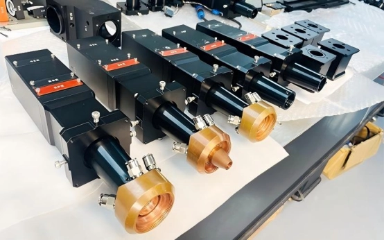
LZ Optical offers tools for larger cylindrical parts. The external surface coaxial powder feeding cladding head supports wide-area coating, repair, and remanufacturing. Internal surfaces require a different approach, with attention to access and powder-stream positioning. The 2-Inch Coaxial Laser Metal Deposition Head is designed for deep-bore cladding applications.
Geometry, Motion, and Head Position
A stable feeder is only one part of robotic laser cladding. Changes in head angle, working distance, or travel speed affect where powder lands and how particles enter the melt pool. These effects are important on curved or irregular parts. The robot and positioner must keep the head orientation and working distance within the validated process tolerance along the full path.
A cladding-head manufacturer should consider more than the optics. The selected head must suit the powder, workpiece geometry, and required operating orientation. Wire-fed deposition should be treated separately because wire systems do not use a powder feeder and therefore require a different material-delivery control strategy.
Add Process Checks to Production
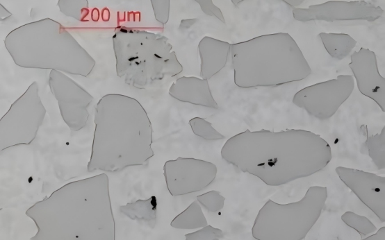
A production-control plan should evaluate both process settings and the finished coating. Record feeder settings, powder batch, gas conditions, laser parameters, travel speed, and head working distance. Compare these records with track dimensions and inspection results. A documented baseline helps engineers identify process drift and investigate it before more parts are affected.
In-process monitoring helps detect variation during deposition rather than only after a part is complete. Depending on the setup, monitoring tools may track the melt pool or process temperature. These tools support process review but do not replace direct powder-flow checks or qualification trials.
Trial Runs and Maintenance
Run a representative test before approving a new powder, feeder, or cladding-head configuration. Use the production substrate and a test piece with similar geometry. Check coating thickness, surface condition, bonding quality, and powder consumption. Record the machine settings associated with acceptable results.
Documented procedures are useful in demanding applications such as laser cladding for mining equipment, where components face abrasion, impact, and contamination. Consistent records help maintenance teams compare repairs over time and investigate changes without relying on memory alone.
Where Powder Feed Stability Becomes Most Critical
Powder feed stability becomes especially important during long-duration continuous cladding, where small flow variations can accumulate over time, and during wide-beam or high-deposition-rate processing, where the required mass flow may be higher. Multilayer build-up also requires repeatable delivery to maintain layer height and coating quality. Long delivery hoses can increase the risk of powder settling or unstable transport, while robotic paths with complex tool orientations can change powder-stream convergence. Internal-bore cladding is particularly demanding because restricted access and tight layer-thickness tolerances leave less room for process variation.
Conclusion
Laser powder feed consistency depends on powder condition, feeder calibration, delivery-line layout, gas supply, nozzle cleanliness, cladding-head design, and robotic motion. Establish a baseline using the production powder and representative workpiece. Record operating conditions, verify delivered powder flow, and inspect the deposited layer. Digital monitoring can reveal process changes, but should be combined with physical checks and routine maintenance. LZ Optical supplies cladding equipment, heads, feeders, and alloy powders. Select the configuration according to part geometry, substrate, coating requirements, and production conditions.
FAQs
Q: What causes powder feed to surge during laser cladding?
A: Material bridging inside the hopper often causes this issue. Poor powder condition or shaky gas delivery will also disrupt the steady flow. Sometimes, hidden blockages inside the hose or nozzle create sudden surges.
Q: How can a plant check powder feed repeatability?
A: First, calibrate the feeder properly. Write down the machine settings and the specific powder batch number. Next, measure the delivered powder flow carefully. Finally, compare the physical coating results across several repeated test runs.
Q: Does robotic laser cladding control powder flow by itself?
A: No. The robot controls motion and tool orientation. Powder mass flow is primarily governed by the feeder, powder condition, carrier gas and delivery path, while the cladding head affects powder-stream convergence and interaction with the melt pool.