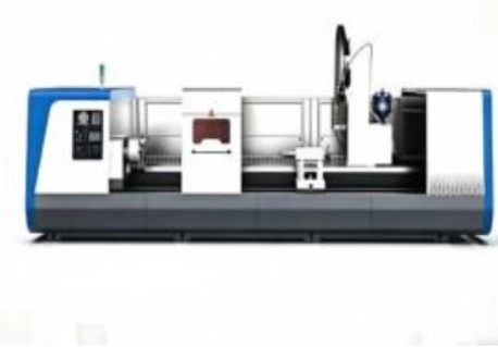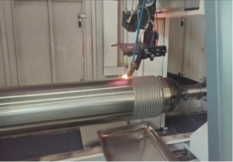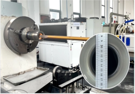
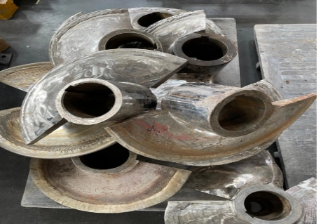
Complex parts are difficult to repair because their surfaces do not behave like simple round bars. A hydraulic support column may be long and heavy. A valve body may have curved sealing areas. A mining component may have local wear, corrosion pits, and impact damage in different positions. In these cases, the repair path is often more important than the machine size alone.
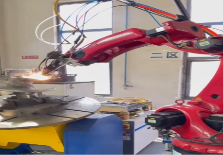
A robotic laser cladding system is useful because it can bring the laser cladding head to difficult surfaces with controlled motion. The robot does not replace process development, material selection, or inspection. Instead, it gives the system the freedom to follow complex geometry while keeping tool direction, working distance, and deposition path within a controlled range.
At LZ Optical, we provide laser cladding equipment, laser cladding heads, powder feeders, alloy powders, and application support for industrial repair and remanufacturing. Our products are used for shafts, hydraulic rods, mining components, valve parts, sleeves, pipes, and other high-value parts that need stable surface restoration.
Why Complex Parts Need Robotic Motion
For simple axisymmetric parts requiring continuous circumferential or longitudinal cladding, a dedicated rotary/linear system may be more efficient. Robotic cladding becomes more valuable when the repair zone involves local damage, changing curvature, multi-side access, or changing tool orientation that requires coordinated motion. In these cases, the robot can keep the cladding head aligned with the surface while following a curved or changing path. Complex parts need a process that can keep the cladding head aligned with the surface while the tool moves along a curved or changing path.
Geometry Drives Robot Motion
In robotic laser cladding, the first step is not choosing laser power. It is checking the geometry. Engineers need to understand where the worn area is, how the robot will reach it, and whether the cladding head can keep a stable working distance during the full path.
A robot can help with:
· Curved surfaces
· Local damaged areas
· Irregular heavy parts
· Angled repair faces
· Multi-side repair zones
· Parts that need robot and positioner movement together
This is why robotic laser cladding is often considered for parts with local repair zones, changing surface curvature, angled faces, multi-side access, or paths that require coordinated robot and positioner motion. Large shafts, hydraulic rods, valve surfaces, mining support columns, and other heavy components may also benefit when their repair geometry requires this additional motion flexibility. The system must bring the laser metal cladding head to the right location without collision, unstable posture, or large changes in deposition angle.
The Technical Core Is Path Control
Robotic cladding is not only “a robot holding a cladding head.” The real value comes from how the robot path is built, checked, and repeated. If tool direction changes too quickly, or if the working distance drifts too much, coating width and layer quality may change.
TCP Calibration and Tool Orientation
Tool-center-point calibration is one of the first technical checks. The TCP tells the robot where the laser spot and powder focus are located relative to the robot flange. If the TCP is wrong, the programmed path may look correct on screen but miss the real melt pool position on the workpiece.
Important checks include:
· TCP calibration accuracy
· Robot repeatability and absolute positioning accuracy
Repeatability does not necessarily indicate absolute accuracy, which may also depend on calibration, robot posture, payload, and workpiece coordinate accuracy.
· Laser head posture along the repair path
· Working distance stability
· Incident angle between beam and workpiece
· Powder nozzle position relative to the melt pool
· Collision risk between head, fixture, and workpiece
· Recalibration after changing the cladding head or tooling
A robotic system can improve coating consistency only when these variables are coordinated with laser power, material feeding, and controlled travel speed. The robot itself does not directly control heat input. Heat input depends on laser power, scanning speed, overlap, beam size, material feed, and dwell time.
Robot and Positioner Coordination Matters
Some complex parts cannot be repaired well by robot motion alone. Long shafts, heavy cylindrical parts, and components with multiple repair faces may need a positioner. The positioner rotates or tilts the workpiece while the robot keeps the head in a stable orientation.
Coordinated Axes Help Keep the Path Smooth
Robot and positioner coordinated motion can reduce awkward robot posture and make the cladding path smoother. This is useful when the repair surface curves around a large part. Instead of forcing the robot wrist into extreme angles, the positioner can move the part while the robot maintains better tool orientation.
Factories should ask whether the supplier can support:
· Robot plus positioner coordinated motion
· Offline programming from CAD or 3D models
· Path smoothing across curved surfaces
· Speed control where curvature changes
· Collision checking before production
· Trial paths before laser processing
· Re-teaching or recalibration after fixture changes
These details matter because a robotic path that looks acceptable at low speed may behave differently during real cladding. Smooth motion helps reduce sudden changes in bead shape, overlap, and coating thickness.
Material Choice Still Decides Service Life
Although this article focuses on robotic systems, material selection cannot be ignored. The robot moves the process, but the coating material carries the service load. A coating for abrasive wear is not the same as a coating for corrosion, heat, or valve sealing.
Match Alloy to the Real Failure Mode
Factories should first identify why the part failed. Abrasion, corrosion, erosion, impact, and high temperature all require different material choices. For compatible steel substrates exposed to corrosion and wear, nickel-based alloy powder can be considered because it supports corrosion resistance, wear resistance, and stable laser cladding performance when process conditions are controlled.
A material review should include:
· Base material
· Coating thickness
· Target hardness
· Wear or corrosion condition
· Powder flowability
· Machining allowance
· Crack sensitivity
· Final inspection method
In laser cladding repair and remanufacturing, material selection must be coordinated with the substrate, service conditions, deposition strategy, and robotic path. A good alloy can still fail if the deposition angle, heat input, or overlap is unstable.
The Cladding Head Links the Robot to the Process
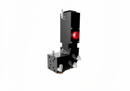
The robot carries the tool, but the processing head creates the cladding condition. Beam shape, powder focus, cooling, working distance, and lens protection all affect deposition stability. This is why the laser cladding head should be selected together with the robot path, not after the cell layout is already fixed.
The Role of the Cladding Head in Deposition Stability
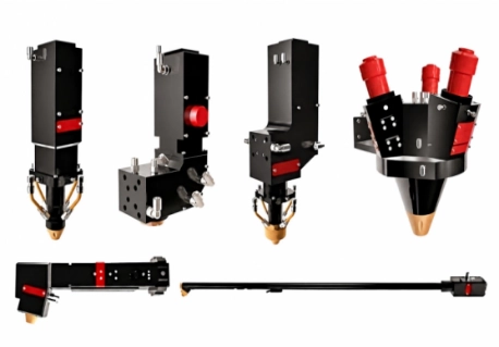
A cladding head manufacturer should explain how the processing head is selected for the workpiece geometry and robotic path. For large external parts, a wider beam may reduce the number of tracks. For narrow internal areas, the head must fit into limited space and keep powder convergence stable.
For large external repair, LZ Optical’s External Surface Coaxial Powder Feeding Cladding Head is designed for shafts, rods, rollers, support columns, pipes, and other wide-area surfaces. It supports multi-layer deposition and thick coating buildup when matched with suitable motion and powder feeding.
For compact internal repair, the 2-Inch Coaxial Laser Metal Deposition Head is designed for confined internal surfaces and deep-bore processing. It is more suitable when access diameter, processing depth, and beam stability are key limits.
Where Robotic Laser Cladding Is Used
Factories usually consider robotic cladding when the part is too valuable to replace, too large for simple repair, or too irregular for a fixed machine. This is common in industries where downtime is expensive and replacement lead times are long.
Mining, Oil and Gas, Valves, and Heavy Equipment
Laser cladding in mining is a strong example. Mining parts face abrasive particles, impact, corrosion, and harsh underground conditions. Hydraulic support columns, cylinder barrels, piston rods, cutting picks, sleeves, and shafts may all benefit from controlled surface repair.
Other common industries include:
· Oil and gas equipment
· Industrial valves
· Hydraulic systems
· Steel and metallurgy
· Power generation
· Marine and offshore equipment
· Heavy machinery repair
· Industrial remanufacturing
In oil and gas, robotic cladding may be used for valve bodies, pump parts, plungers, pipes, and drilling tools. In valve repair, it can restore sealing surfaces where controlled dilution, coating thickness, and final machining are important.
Robotic cladding can support industrial remanufacturing strategies by restoring material only where repair is required. This makes it useful for factories trying to reduce replacement pressure and recover high-value parts more efficiently.
Product Categories Behind a Robotic Cladding Cell
A robotic system is not just the robot. A complete cell may include a laser source, processing head, powder feeder, cooling unit, positioner, safety enclosure, path software, monitoring devices, and inspection tools. The equipment should be selected around the part family, not only around one sample.
Equipment, Heads, Feeders, and Surface-Processing Options
LZ Optical’s laser cladding products include laser cladding equipment, cladding heads, powder feeders, alloy powders, and related surface-processing tools. These product groups can be combined for robotic laser cladding, internal bore repair, external surface rebuilding, and surface strengthening.
A typical robotic cladding project may involve:
· Robotic laser cladding equipment
· External or internal laser cladding head
· Powder feeder or wire feeding module
· Alloy powder matched to service conditions
· Positioner for heavy or rotating parts
· CCD molten pool monitoring
· Adaptive height following
· Closed-loop temperature control
· Offline programming and path validation
Related surface-processing solutions may also include Laser Hardening Head for Surface Treatment when the part needs local hardening rather than material buildup.
How to Evaluate a Complex-Part Cladding Application
Before choosing a robotic laser cladding system, factories should prepare enough information for a technical review. A clear application file helps the supplier judge robot reach, fixture design, path planning, material choice, and inspection needs.
What to Prepare Before Technical Review
Useful information includes:
· CAD drawing or 3D model
· Workpiece dimensions and weight
· Base material
· Worn area location
· Damage depth
· Required coating
· Target coating thickness
· Batch size
· Final machining requirement
· Photos or video of the part
· Current repair method and failure problem
The technical route usually follows this chain:
Geometry -> Robot motion -> Tool orientation -> Working distance -> Path planning -> Coordinated axes -> Process consistency -> Complex-part validation.
This chain is a useful way to judge whether a robotic cladding proposal is realistic. If any step is weak, the final coating may become unstable even when the laser, powder, and robot are all high quality.
Conclusion
A robotic laser cladding system is valuable for complex parts because it connects flexible motion with controlled surface repair. It can follow curved surfaces, reach local damage zones, and work with positioners for heavy or irregular components. But the robot alone does not guarantee coating quality. The result depends on geometry analysis, TCP calibration, tool orientation, working distance, path planning, cladding head selection, material choice, and final inspection.
For factories repairing shafts, hydraulic rods, valve parts, mining components, sleeves, rollers, and oilfield equipment, robotic laser cladding can reduce replacement pressure and support repeatable remanufacturing. The best results come when the robot, cladding head, powder, process parameters, and validation method are developed as one complete repair solution.
FAQs
Q: Why is a robotic laser cladding system useful for complex parts?
A: It controls tool orientation and path movement across curved or irregular surfaces.
Q: What data is needed before robotic laser cladding?
A: CAD model, dimensions, material, worn area, target coating, thickness, batch size, and photos.
Q: What affects robotic cladding consistency most?
A: Geometry, TCP calibration, working distance, path planning, coordinated axes, and process validation.